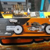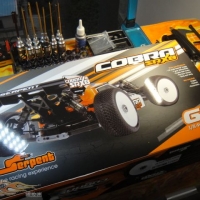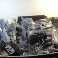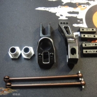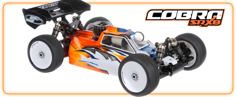
This build was sent in by John Ho, the way this was done was originally on a forum so instructions with each picture, look at pictures and instructions here separately.
Unboxing:
Diff builds:
The diff design on the SRX8 has been completely re-vamped. The design philosophy of Billy Easton is simple: By not increasing the size of the diff cases (hence weight), but at the same time improve the consistency of the diff performance in a long race, Billy came up with the idea of “compensator”, to absorb the pressure built up by the diff when running a longer main. At the same time, the internal gears have been fully re-designed, profile and teeth count had changes to improve smoothness, result in a diff that are much smoother compared with the one used in the previous 811.
- First of all, we cut the compensator into a strip according to the manual.
- We can now put them inside the diff, now you will understand why we have so many “holes” on the diff case.
- Serpent has changed the supplier of the bearings, and you can tell they are of a much higher quality.
- Apply grease on the diff cup axle.
- Then place the O-ring inside the diff case.
- The construction of the diff gears has been revised too, it no longer touches the O-ring directly. The length of the pin guarantee the shims will not wrap after long use.
- The shape of the diff gears are designed to hold diff oil better, it’s also been hard coated
- After the O-ring, we then install the shims.
- Then we install the out drive, and install the pin
- You can see the length of the pin cover the full diameter of the shim.
- We then install the gears.
- Now is the time to install the set screw.
- The profile of the satellite gears are all new, Serpent has done a lot of testing to ensure a smooth diff, and also added shims behind it so you can fine tune the gear lash.
- Again, the profile of the main gears are also all new.
- Same with the diff case, we first install the o-ring.
- Then the shim.
- Pin, follow by placing the gear on top.
- I always coat the gasket with silicon oil
- The manual gives clear figures on how heavy the diff should weigh
- I always install a few threads on the screw, make sure it’s straight first and check whether the diff will rotate smoothly
- I then tighten it up, but not fully yet, then we will tighten it up one by one on a cross pattern to ensure the correct fitment.
- I always write down what diff oil I am using and mark down whether it’s a front or rear diff.
- You can see all 3 diff are finished.
Part 1: Diff finish see gallery below.
Part II center diff mount
The design philosophy of the center diff mount are simple: making the adjustment of the brake easier and a sturdier construction.
- All the parts lay-out
- The Diff mounts are “back to basic”
- The top plate is brand new, it serves the purpose of protecting the brake assembly from fuel.
- For some of the engine brands, you may have to cut off this portion to avoid touching the carb.
- Pre-glued brake pads
- To install the brake pads, we will need to utilize these special screws. To ensure the smoothness, the design includes a gliding tube so the pad will not get drag on the screw directly. It’s also super easy to install, just tighten the screws and the gap of the brake pads will be perfect.
- Return springs are included, the springs are specially designed so the end of it will not trap inside the brake pads holes, that’s what we call attention to details.
- A photo to show you how it actually looks
- Just tighten the screw up, then it’s done
- You can see the gaps are perfect
- The brake disc are made of steel, a disc guide is also new on the SRX8
- With the disc guide in place, the disc will not fall out
- The only thing you have to pay attention to is the direction of the center diff, all other steps are simple.
- The center diff plate, which I will talk about later.
- The chassis are now hard-anodized, and greatly improve the chassis durability.
- Laser etching just make it looks that little bit nicer
- Now we will talk about the center diff plate.
- Made of steel, it actually helps to lower CG, at the same time, it makes gear lash adjustment a no brainer. Even if you need to remove the center diff for maintenance, it won’t change the gear mesh at all.
- For the Alpha engine I need to install later, I have already cut out the portion on the right
- We finally have a proper filter mount 🙂
- Brake rod are made of spring steel, the longer one should install at the front of the diff.
- Install the cover, make sure you do not over tighten the 4 screws, fail to do so will affect the smoothness of the brake action
- Very traditional brake wires.
- Make sure you will apply thread lock on metal to metal surface
- We are now done with the center diff assembly.
Center diff mount Gallery
Part III – Rear Gearbox
The gear box is completely re-designed and show no resemblance with the 811 series. We will start with the rear gearbox.
- As we mention earlier, the structure and shape of the gear box are totally different, Serpent has eliminated the need for the 3 screws design and go to a more conventional way. The outer shape of the gearbox is more muscular compared with the old one.
- A quick release design, the cover can be removed by removing 4 screws only.
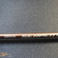
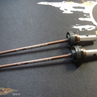
- You will need the only 96mm CVD for the rear-center , all others are 98mm
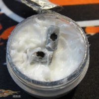
- Since there is dust covers for the CVD’s, you can go heavy on the amount of grease you are going to use.
- A brand new design coupler, with two sets of locations for the connecting pin, hence increase the life span of the said parts by 2 fold.
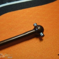
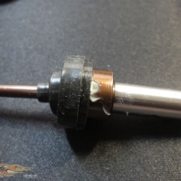
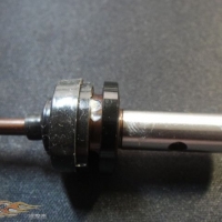
- The CVD pins are designed to be used without a set screw, with the bearing installed it will never fall out.
- The dust covers are completely new and made with much softer materials, minimize the drag it will cost on the drive train. Be very careful when pulling it on to the CVD.
- Pay attention to the dust cover correct fitment.
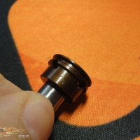
- The sleeve will then hold the dust cover securely, at the same time it will reduce the chance of the set screw getting loose.
- You can use shims to adjust gear lash, however for a brand new build I will recommend not to use any.
- Again, after long term testing, the new bearings prove to be far superior then the previous ones.
- We have to ensure the true and tight fitting for the bearings, make sure the drive train is free.
- As mentioned earlier, a much simplified construction.
- Utilizing 5mm set screw.
- The body post is a new design, which is floating to avoid body sheer on the mounting holes.
- This is how you will fit the o-ring on the base of the body post.
- With again, a special type of screw.
- You do not have to tighten it up completely, so it can work the way it should.
- The screw for the body post is tightened inside, so make sure you do it before you put the diff in.
- With the center rear CVD install.
- Now you can drop the diff inside, some grease will always help.
- Then the cover “push” in place for a perfect sealing gear box.
- 5mm thickness CF towers, with brand new geometry design.
- You don’t have to tighten these two screws yet.
- Arm mounts are again brand new and made of 7075 Alu.
- Some fixture posts to aid the alignment.
- The rear gear box complete
Rear gearbox gallery
Part IV Rear arms
- Whats included for the rear arms step
- As for the design of the rear arms, thinking was simple: it should be strong enough to use without any additional plate, but at the same time, our customer can use different plates to adjust the hardness of the arms.
- Droop screws are made of spring steel.
- And you can adjust it both ways.
- One of the very few parts that carry over from the 811 series, the ball and cover for the anti-roll bar.
- You only need to tighten it up till the ball can just move freely.
- The plate that is included with the arms, please note the upper and lower plate do have different screw hole patterns and are not interchangeable.
- We use round head screw so the plate can still have enough materials left for the screw to hold down, making it less easy to deform.
- This is how your arms should look.
- Make sure the ball cup are perfectly straight when you are installing it.
- And you can use a caliper to measure the correct dimension according to the manual.
- All the pills are completely new and are dedicated to their own arm mount. You can also tell your setting by only looking at the pills due to the fact that we have now print out the correct figures on the pills itself.
- For example, this will be the 2 degrees anti-squat pills.
- The arm pin are the same with 811
- To ensure tightness, the arm mounts are secured by cap-head screws.
- Please note the direction of ball cups, you should always fit the ball in on this side.
- The kit came with a 2.3mm anti-roll bar.
- Bearings on all anti-roll bars, which becomes a signature design with the Serpent line-up.
- Very nice fit!
- Now you can push through the roll-bar, and placing the lock cap in place.
- The kit also includes a Lexan mud guard.
- With the roll-bar in place, this is how it should look.
- The rear up-rights are one of the kits highlights.
- Made by 7075, fully CNC machined and lightened, with chamfered edges, it’s a master piece and I cant believe this is actually included as a standard kit offer.
- As mentioned earlier, 98mm CVD will be used.
- Another improvement which you may not notice, the CVD’s are actually thicker close to the ball side to minimize breakage.
- Again, please be careful when you install the dust cover.
- More grease, more grease…
- Same with the center, the drive cup also offers two sets of holes.
- By turning it a few times, the grease will spread more evenly.
- Pay attention to the proper position of the dust cover.
- Another new feature: the locking ring of the dust cover, also serves as the locking ring for the CVD pin.
- The uprights use two different size of bearings.
- Beefed up connecting pins for the 17mm wheel adaptor, it’s now 3mm.
- Again, please use thread lock for this.
- You can also adjust roll-center by changing the position of the hubs.
- With the two sets of inserts, you will have 4 different positions to choose from.
- Another feature that I like very much, you can see the roll setting from the out-side of the hub…
- With twin set screw design, we can guarantee the pin will not rotate inside the wheel hub, thus increase the life-span of this beautiful part.
- With a lock nut, the arm pin tightness can be fine tune.
- Here come our new wing mounts.
- Again, pay attention to the direction of our ball cup.
- With a proper tool, you can ensure the easiness of fitting a ball cup.
- Evidence of no cost being spared: the balls are all made of Alu. with hard anodized coating.
- I always prefer to install all the balls into the ball cup first.
- An interesting feature, the SRX8 actually came with hard-anodized Alu. linkage…But are they strong enough?
- You bet! With 5mm thickness, it performs beautifully in all our tests and no breakage have been reported.
- And the reason for Alu.? Because they are very very tight.
- The notch tells you this is the side with the normal thread.
- The thing I hate most when building a car is building all these tie-rods, so I am gonna tell you a “lazy” method. I will first screw in a few threads on both side.
- Then I will install it on the car…
- By the way, the screws now are long enough to fit a lock nut, to eliminate the tie-rod becoming loose in a long run.
- On the other side, you only need to push the screw through, no need to tighten it up yet.
- Pay attention to the CVD position.
- Now you can start to tighten the tie-rod up to the desired length.
- And hola, much faster then normal!
- Now you can tighten the lock nut on the hub.
- The new one pıece wing mount. After numerous testing, we can conclude it’s a super solid design.
- These are all the screws you need.
- Another trick: use a 2mm driver to help push the lock nut in place.
- The correct length of the screws that you should use should end up like this.
- Done~~
- The cut outs are for…
- …A dust prevention gasket. I will normally rub it with grease so it can protect dust from entering even further.
- Another feature: The SRX8 came with a steel made rear end chassis plate, again to help increase the life span of the chassis.
- I will first install these two shorter M4 screws
- Then the two longer ones which go all the way to the diff cover.
- Then tighten the two M3 screws from the front.
- Now the rear-end is completely done.
Rear Gallery
Part V Front gear box
- Whats included
- Again, using 98mm CVD, easy to keep parts count!
- The covers however do look different compared with the rear gear box.
- The gear case itself also looks different.
- The installation methods are exactly the same with the rear, so I will not repeat it again.
- Now come the front arm.
- We have to enforce all the right places to make sure a strong arm.
- Same with the rear, make sure it’s smooth.
- Install the droop screws.
- The arms are complete.
- Same with the rear clips, all pills are a different design.
- I have built the car according to the manual, hence we will use the 10 degrees kick-up setting.
- Everything just goes on so smoothly.
- The front roll bar is 2.3mm.
- Again, tighten the set screw.
- The design for the steering is all new, for the SRX8 it uses a traditional C-Hub design in order to achieve better physical steering angle.
- When I tell you the SRX8 is full of goodies, I do mean it… Full Alu.7075 C-Hub and steering knuckles are standard, complete with CF ackerman plate!
- The CVD build is exactly the same with the rear, so I will not repeat here.
- You will find different option ackerman plates on Serpent site now.
- 3,5mm thickness, I will challenge you to break it!
- The knuckles, as the rear-hub, are beautifully made!
- The C-Hubs that come with the kit are 15 degrees, and you can find 13 and 17 as an option in the future.
- There are screws that you need to install to limit travel, please remember to install it.
- These parts are made by POM to ensure smoothness.
- And you will find markings on the knuckles to determine left and right.
- Same with the C-hubs.
- A very traditional king-pin.
- However, you can see some small details here, the flattened part is where it should face the set screw.
- Same with the rear, the C-Hubs they also utilise twin set screws to lock down the pin.
- The manual calls for a 0.4mm shims, however after testing, we prefer to not install any shims. However, with the shim your car will be a lot more stable.
- The linkage.
- Continue to use my “Lazy” method.
- So it’s done in no time!
- I always put some grease in this area to prevent dust entering the gear box.
- Brand new designed front bumper, minimizes any chance of deformation upon impact.
- Using the same 4 M4 screws to tighten the gear box with the chassis.
- Again you leave the front screw to tighten later.
- The car finally starting to look like a proper buggy.
- The steering post design are the same as older 811.
- The angle on this part actually minimises the effect of bump steer.
- Remember to use thread lock when installing these parts.
Front Gearbox gallery
Part VI Steering assembly
- We will now go to Servo saver, steering linkage etc.
- What’s included.
- The tensioner for the Servo saver is now equipped with screws to clamp it down.
- The bearing for the steering plate are now pre-pressed to completely eliminate sloppiness.
- Again, hard-anodized ball.
- The design is very beefy.
- First we will install the saver post.
- Then the spring.
- Then the dust protecting foam.
- Again, with the right tools, it’s really easy to tighten the clamp.
- We will measure the distance according to the manual suggestion.
- And I will make sure the clamp tightening screws are facing outwards just in case I need to re-adjust it.
- Don’t forget the shim underneath the bearing.
- You can now press in the lock nuts.
- Pay attention to the ball cup direction.
- Because the ball cups are quite long, to avoid twisting it while building it up, I will suggest not to use my “lazy” method here.
- And pay attention to the screws length as they are different.
- Again, don’t miss out the shim.
- Pay attention to the direction of the ball itself.
- Now you can put the bearing on the steering post.
- Then the whole assembly, and you can now put the upper bearing in place.
- To achieve the proper bump steer effect, make sure you have put the shims on the steering arm.
- The complete front end is done.
Steering assembly gallery
Part VII Side guard and stiffener
- We will now move to the side guard and chassis stiffener.
- The brand new designed triangular front plate.
- Please note the direction of the front body post.
- The stiffeners are utilizing lock nuts.
- You need 3 of them for the front stiffener.
- First attach this screw, but you don’t need to tighten it up yet.
- All M4 screw for the triangular plate, pay attention on the different length.
- Tighten the screw on the chassis.
- Then tighten this screw to guarantee perfect alignment.
- You will need a 3mm Hex tools for the rear stiffener screw.
- Again, don’t tighten the lock nut just yet.
- Wait till you have tightened the screws on the chassis, then you can tighten the lock nut.
- The side guard attachment method has been revised. Now the screw will come from the top, which makes it easier to remove.
- I will use a 1.5mm hex tools to put thread lock inside the side holes first.
- Be careful with the angle on the chassis, as the screw will have to come in at an angle too.
- You only need to tighten the screw till it’s flush with the chassis.
- The fit is very very nice.
Side guard and stiffener gallery
Part VIII Servo installation
By moving the battery position more forward has been the key, at the same time, it’s a lot easier to get to the servo on the SRX8.
- What’s included.
- I am using Highest rated servos for my installation.
- The servo steering arms are much stronger and beefier compare with the 811, however I still prefer to use an Alu. option just to be 120% sure.
- The different thickness plates have been provided, and you can use this to adjust the height of the servo. The key is to avoid the servo touching the chassis at any time.
- For my servo I’ve got, plate number 3.
- The servos are very very easy to install.
- Make sure the wires are routed in this manner.
- AMB transponder has it’s own place, Serpent even provide an AMB holder specially designed to accommodate the newer smaller AMB’s.
- You can see the battery are all the way forward now to aid steering response.
- Since I don’t like to use a switch and prefer a direct connection for the batteries and receiver, I need to do some modification on the battery cover.
- Now the battery. wire can came out even when the cover is fully closed.
- Then I haveto prepare an extension wire from the receiver.
- I then use the original switch covers, and using CA to glue a “plug Locker” on top.
- The end result is very nice. You can still use a plug and Serpent did provide a silicon cover for the plug to prevent dirt getting inside the receiver compartment.
- The Servo boxes will use M4 screws to attach to the chassis.
- When you install the steering linkage, make sure you do not forget the shim.
- Again, a more traditional approach towards the throttle and brake linkage. All you need to do is follow the instruction manual and it’s really pain free to get it right.
- Pay attention on how the servo horn should look when it’s in the neutral position.
- New for the SRX8, springs and bushing to improve the “feel” on the braking.
Servo install gallery
Part IX Shocks
The shocks on the SRX8 are a completely new design. By utilizing C clips, we can now guarantee the pressure on the internal o-rings and shims will always be the same and will not be affected by how tight you actually screw the end cap.
- What’s included.
- Wow, CNC machine derlin shock pistons are standard issue for the SRX8! It came with 6×1.2mm holes.
- To address one of our problems before, the pistons are now secured with lock nuts, we no longer need to worry about the piston coming loose.
- They have also down-sized the shock shaft from 4mm to 3.5mm, effectively increasing the volume of oil we can put in the shock body itself.
- The newly develop X-ring,
- Even the shims are full CNC derlin. Pay attention to the direction though. This shim will go in first.
- Then the first X-ring. Some green slime will help the smoothness and minimize leakage after a long run.
- Another shim goes in, this time a flat one.
- You will now put the second X-ring in.
- Now install the final shim.
- You will now install the c-clip, I found it easier if I am placing this end inside the groove first.
- Add some silicon oil on the thread portion of the shock shaft as it will prevent premature wear on the X-ring.
- With the newly designed shock body come the matching new shock boots, which are made of a different material compared with the one used on the old 811.
- You will have to install the shock boot first, then the shock end.You can see the shock boot no longer needs to attach to the spring cup, this in turn improves the life span of the shock boots.
- Then you can measure the shock length, make sure it’s the same left and right.
- Now you are ready to fill it with oil.
- Remember to install the O-ring inside the spring collar.
- I always put a drop of silicon oil on top of it, to ease the turning.
- You can now move the piston up and down to release the air trapped underneath the piston. Leave it a few minutes until all air bubbles disappear.
- Then you can slowly tighten the shock cap, till the point you can start to feel a little tightness.
- At this very moment, you can then push the piston all the way up to push all excess oil out, while at the same time tighten the cap fully.
- You can then check the pressure on both shocks to see whether they are balanced or not.
- They have also increased the height of the spring cup, to prevent the spring from moving out after a hard crash.
- The shock posts are again made of alu, and hard-anodize treated.
- Serpent even provide an alu base for the cap screw to spread the load even better.
- How it looks when installed on the shock tower.
- The connecting pins are also improved from 3mm to 3.5mm
- They have now moved the set screw towards the back of the shocks to further improve the strength of the arms. One set screw hole for two shock position,
Shock build gallery
Part X Fuel Tank
- The fuel tank is also a brand new design.
- It came with a puller, still using a floater to prevent flame out when the buggy is upside down.
- With a proper sanctioned race, you can install this spacer to make the fuel tank legal on 125cc.
- All the clips are now screwed in, makes it a lot more solid compare with the older 811 tank.
- And make the fuel line routing that much nicer.
- The rubber grommet also prevents vibration and minimizes foaming.
- One of the fuel tank posts had a channel built in for excess fuel to flow through.
- Both posts are designed to be locked in position so you will not need to clamp it while tightening the screws on the chassis.
- Use this special type of screw to fix the fuel tank on the post.
Fuel tank gallery
Part XI Engine installation
We have now finished the chassis, the last part will be fitting the engine.
- What’s included.
- I am using an Alpha engine.
- The clutch is the same as the older 811, a 4pc design. The kit came with 4x plastic , but I always prefer 2x alu and 2x plastic set up.
- Pay attention on how the springs should be installed.
- To aid the process, press the portion like I did on the photo, then you will find out the screws will be a lot easier to go through.
- It’s actually very easy to install.
- My engine came with a long sleeve.
- But we should really need a short one.
- Since it’s a 4pc clutch, we cannot use the conventional clutch tools to lock down the fly well, hence I am using a fly-wheel removing tool to lock it down.
- All you need to do now is tighten the lock nut in the middle.
- Even the clutch bearing is made by NSK…
- I always use some cleaner to clean up the clutch bell first.
- You can now use the shims provided to adjust the free-play.
- Next up, you will have to adjust the angle of the carb.
- Also the position of the carb puller.
- You can now install the engine to the engine mount, but no rush to tighten it up.
- I will also install the exhaust now.
- You can now fit it to the buggy.
- This is how you should set up the throttle horn, everything is in-line nicely.
- You will also have to check whether the throttle linkage is on the same plane as the carb puller.
- The exhaust wire holder are also improved compared with the older 811s’
- We now utilize two fixture screws so it won’t turn.
- They have also increased the size of the set screw to 5mm.
- Done!
Engine installation gallery


