
The Car:
To see the car and all details go to Serpent’s website here
Build sponsored by:
Serpent
SerpentUK
Arrowmax-RC
RudeBits
Team-NCRC
AM-410116-BG Allen Wrench 1.5 X 100mm Black Golden
AM-410121-BG Allen Wrench 2.0 X 100mm Black Golden
AM-410126-BG Allen Wrench 2.5 X 100mm Black Golden
AM-410131-BG Allen Wrench 3.0 X 100mm Black Golden
AM-450145-BG Nut Driver 4.5 X 100mm Black Golden
AM-450150-BG Nut Driver 5.0 X 100mm Black Golden
AM-450155-BG Nut Driver 5.5 X 100mm Black Golden
AM-450170-BG Nut Driver 7.0 X 100mm Black Golden
AM-190014 TURNBUCKLE WRENCH 3MM-4MM-5MM-5.5MM
AM-190025-B MULTI SHOCK-CLAMP V2
Optional:
AM-171063 Multi Alu Case For Screws (120X80X18MM) Black Golden
AM-171053 Tools Base Black Golden
AM-500902 Power Tool Tip Set 4 Pieces With Plastic Case (Metric)
Setup and build manual used:
I will be building as per manual but using Tony Evdoka’s setup for Maritime uploaded on his website here 3rd January 2017 also available on Serpent’s site here
The manual has had a few updates so make sure you download the latest one here at this time it is dated 09/01/2017
PetitRC Setup Sheet: Arno has made a nice easier editable setup sheet for the SDX4 Download from his website

Body and wing: RudeBits R2 wing and Thanks again to Tony for sending the R2 Wing and arranging the paintwork, paint done by Jim Currie and #Sickgrafix excellent detailing in the body, I love it.


Notes:
In my build I used the shocks from one of my MM buggies as they are close to the pro shocks, this is just a personal choice and I have not heard of any problems with standard shocks.
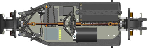
Layout options: There are some nice options on layout to distribute weight for different surfaces, I will use Layout 1. If you use layout 4 your wiring will need to be longer so be aware.
-

- Layout 1

-
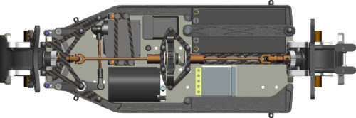
- Layout 2

-
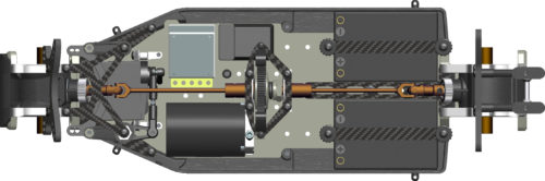
- Layout 3

-
- Layout 4 Saddle packs

Rear Shock Positions: Also shocks can be front or rear mounted on the rear of the car.
-
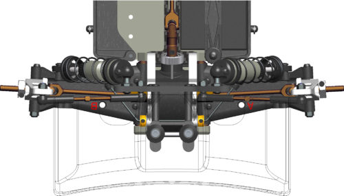
- DEF shocks to front

-
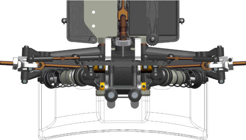
- OPT shocks to rear

Extra holes for rear shocks: With the rear arms you have 4 mounting positions by swapping left arms with right arms so instead of the usual 2 holes you now have 4 holes to choose from.
-
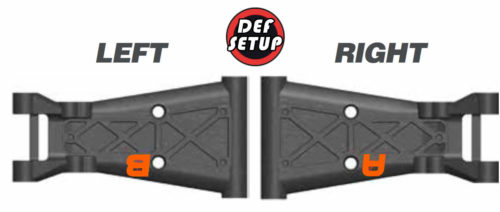
- Holes further out

-
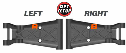
- Holes further in

Build Tips:
STEP 6: If you want an easier way to align the holes use 2 m3x18 screws to align not just 1.
STEP 10: This shows you that if you swap right with left you will have another 2 shock positions giving a total of 4 ways to mount shocks. To me it was not clear but after speaking with Tony I realised.
STEP 11.2: When tightening plastic nut make sure free movement. So do not tighten completely. There will be no droop on the car if too tight.
STEP 18: Do not over-tighten the lock nut as this will clamp the mounting and you will not have free movement.
STEP 20: I suggest the best tool on the market. Part number 190504 to attach ball ends. Before fitting ball cups and rods on the car put each end on the outside ball and squeeze cup against the ball with flat not serrated pliers as they are a tight fit and you need it to have free movement NOTE: If you do this to the cups please be careful, I always do it and do not damage plastic cups.
Also put balls on before mounting shock tower just easier.
-

- Perfect tool

-

- Pinch gently

-

- Do not be brutal

STEP 21: Make sure holes are lined up for alu wing mount as there is no way to turn them afterwards. just put a screw through to make sure.
STEP 28: I put all 4 grub screws in relevant parts before assembly as makes it easier to fit but make sure they are loose.
STEP 29.1: Use the shorter of the ball ends there are two longer ones so don’t get them mixed up.
STEP 29.2: Just nice to see the hubs are stamped left and right (5L and 5R).
STEP 31: Message from Tony Evdoka. Make sure when looking from the front of the car, the turnbuckle is fitted to the rear of the tower – It looks like its in front on the drawing
STEP 32: There is no measurement here for servo saver adjustment. Tony Evdoka says wind it up as far as it will go by hand.
STEP 35: Make sure the washers are upside down. in other words flat surface facing upwards.
STEP 36: With my low profile servo I only used 1 washer on each screw as when I used all washers the servo arm was touching. Servo is Sanwa ERB-871. Obviously different servo’s require different spacing.
STEP 38: Squeeze the slipper spring before installing and open and closed for a few times . Ideally leave overnight in a vice if you have one.
STEP 40: Make sure you understand the layout you will use. As mentioned I am using a setup from Tony Evdoka.
STEP 41: Loctite both grub screws as they are under a lot of pressure and you do not want them coming out.
STEP 42: Make sure you understand the layout you will use. As mentioned I am using a setup from Tony Evdoka.
STEP 42.1: Tony Evdoka and Darren Lewis (team driver Serpent UK) say “the little ears as I call them that hold the wires away from the spur. They can also be turned upside down and fit under the carbon so the wires are kept low.”
STEP 44: I used the shocks from my MM buggy as they are close to the Pro shocks. I recommend the pro-shocks for long lasting racing success. Part numbers 500644 http://serpent.com/product/500644 – 500645 http://serpent.com/product/500645


If you are fitting kit shocks I personally don’t like the oil seals that come with the kit (if red) Remove completely or replace with 500179 I Had issues before where these red seals got sucked through piston holes and locked up the shocks. Removing prevents and there are no leaks.


STEP 45: If using kit shock pistons make sure when you loctite the nut on the shaft do not tighten nut too much or you may squash the piston which will change its shape.
STEP 48/49: I always use the Arrowmax shock pliers to press the collars into the shocks AM-190025-P MULTI SHOCK-CLAMP V2


STEP 51: The motor screws were way too long so make sure you have shorter ones available.
STEP 52: My shorty pack was a little loose so Tony Evdoka suggests if you are worried about it then Add a piece of 500280 to the chassis and that will help but still flex. If too tight it will stop flex so this way you avert this and have piece of mind.
STEP 55: The body pins protrude below the chassis even though they are small clips, I will probably use Velcro for the body as I do not want the pins to grab on the track surface. Or use Tony Evdoka’s tip and re drill the holes to the side.
A picture of my car: Also showing Body pin mod that Tony Evdoka suggested

Video Gallery:
Build Gallery:


